
Author

There are several ways to create a new page, but the easiest is to use the page navigator. The page navigator is displayed by default, if not, it can be displayed via the Home tab > Page group > Navigator. The new page command is also available in the same command group: Page.
To create a new page via the context menu, right mouse button > New.
The next step in the process is to select its "Full page name", “Page type” and “Page description” in the new page dialogue.
The prepopulated values are based on the page on which the context menu was invoked, and the “Full page name” is prepopulated to reflect the page directly after the selected page.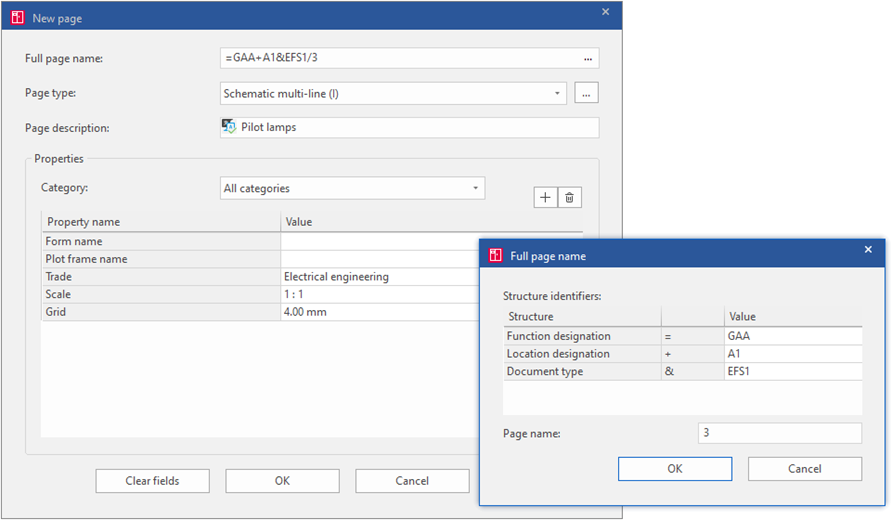
"Full Page Name”
The first field “Full page name” defines the structure of the new page, and through it the devices drawn on that page are also included. For simplicity, it is advisable to click on the button with three dots on the right and select the required values.
The most frequently used aspects of the structure (depending on the project settings) are:
Function designation
This is based on the standard IEC EN 81346 part 1 and facilitates orientation in diagrams by dividing the entire project into smaller functional units. It is advantageous to use divisions that designers and customers as a whole can recognise. For example, if a project is proposed to have some defined options, it is suggested to use a Function Designation for each of them. Likewise for the sub-functions that make up the rest of the machine or technology.
Location designation
This is also based on the standard IEC EN 81346-1 and divides the project pages and devices into smaller "physical mounting areas". In electrical design, it is often about the labelling of the enclosures, cabinets, machines etc. It can be said that if a partial parts list is required to be generated, it should be possible to establish a special location marking for it.
Document type
The type of document is based on the standard IEC EN 61355-1 and the project pages are divided into individual classified designations These types are grouped into larger logical units, such as schematics, Layouts, reports such as diagrams, parts lists, connection lists, etc.
Page name
The last field is the page name. This can be misleading as it's better to think of it as a page number for two reasons. Pages are sorted by this name in the project, and it cannot be filled in multilingually, which is necessary for description fields such as Page Description. Pages can also be decimal or alphanumeric such as 1.1 or 1.a, etc.
“Page Type”
The page type is probably the most important selection. It defines whether the inserted pages will have diagrams with connections in it, whether it will be an overview for example of a PLC, or whether it will be a purely graphic page. Below are the most used page types for electrical design and what can be expected from devices therein:
Schematic Multi-Line/Single-Line
The devices inserted here create automatic connections between them and are displayed in the device navigator with the representation type Multi-line or Single-line, and thus are reported in the parts list.
Overview
The devices inserted here do not create connections between each other but are displayed in the device navigator with the representation type Overview and are taken into account in the parts list.
Graphic
Devices in the graphics page neither create connections nor appear in the device navigator, and therefore are not reported in parts lists or Bills of Materials.
Panel Layout/Model View
These page types are used to display the layout of devices in an enclosure or cabinet.
External document
As an external document type page, a link to any file can be attached, which opens in its own associated application after opening the page.
“Page Description”
In the Page Description field, there is an icon on the left showing that the field is translatable. These types of fields can also contain special characters such as diameter (Ø), degree (°), plus or minus (±) etc. These fields can also be edited in multiple languages which can be used later if the project needs to be translated into other foreign languages (right mouse button > Multilingual input).
“Properties”
At the bottom of the dialogue is a property table that also remembers the properties from the previously selected page. The Plot Frame Name property is normally left blank so that the standard plot frame is used. This is defined in the project settings (File > Settings > Projects > Project Name > Management > Pages).
Discover the wide range of courses at the EPLAN Training Academy to learn how you can get the most out of the software and use it effectively.

Comments