
Author

There are many types of navigators in the EPLAN platform, one for each type of device such as terminal strips, cables, PLC’s etc. In this article, all types of devices will be displayed.
The device navigator can be found in the Devices tab > Devices group > Device Navigator command.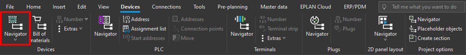
Note: In the following text, default settings for displaying structures are assumed. It is possible that different projects have different settings and not all the structures are displayed, or they might be in a different order.
The device navigator displays the devices inserted into the project, sorted by structure based on their Full DT. In the image below can be seen the devices from the function =GL1 (Feed workpiece: Transport), also has locations: the contactor -QA1 is in the enclosure marked +A1 and the motor -MA1 in the location marked +B1.
The most important icons from the device navigator
In the example of the contactor in the above image, are the most common icons that will be seen in the device navigator:
Main function ICON
In the previous article, How to insert a symbol or device into a diagram, it described the main function, and that each device must have only one. It is the function in which parts (items in the parts list) are defined, and it is indicated by the shopping cart icon.
Auxiliary function ICON
Each symbol placed into a multi-line diagram consists of a function and is represented by a cube icon in the navigator. In the contactor example, these are individual power contacts, but they can also be device connections, a thermal switch of a motor or auxiliary contacts of circuit breakers.
Function template ICON
If the main function has an associated part complete with function template data filled in, then these templates are shown in the navigator in one of two ways.
- They are paired with the placed features from the schematics and appear as a small triangle superimposed onto the feature's "cube" icon. This is the ideal state needed to be achieved i.e., the placed item (features - cubes) is paired with what the item is actually linked to (templates - triangles).
- They remain as triangles i.e., a function template that has not been used. They can be unused cable cores, contactor contacts or even PLC connections. This is not an error, only an indication that there are spare functions that can still be used elsewhere. On the other hand, if the functions (cubes) remain without a template (triangle), that is something that is placed in the diagram, but which the assigned part does not provide for it. For example, an error in the use of a normally closed contact or an error in the numbering of the terminals. This is the type of error when the device cannot be manufactured/connected according to the schematic.
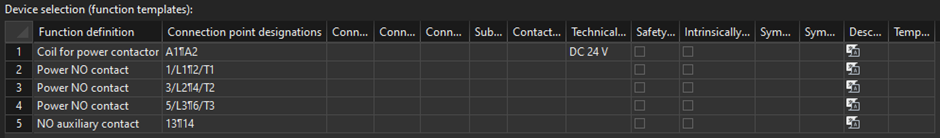
Sample function templates are defined in the parts database for a sample contactor.
These function templates, which are not yet drawn in the diagram, can be placed directly from the device navigator into the diagram by dragging with the mouse. With this procedure, there is full control over which contact/connection of which device is placed where, and the correct visible marking appears on the symbol, so that the pairing is maintained. EPLAN takes care of this.
Function representation ICON
This icon shows the representation of the device in an enclosure (3D EPLAN Pro Panel model or EPLAN Electric P8 2D mounting panel). It shows that the device has been placed in an enclosure. It is mainly used in the device navigator in conjunction with the 3D design of the assembly and works as an easy link to the model.
Unplaced function ICON
For functions that are drawn in the diagram, it is possible to delete only their placement ([Alt+Delete] or the tab Edit > Clipboard > Delete > Placement). This removes the symbol from the schematic, but the function remains in the navigator for later use and dragging back into the schematic.

Two functionally similar icons have now been identified: an unplaced function and a function template. The difference is simple. The function template only contains data common to all occurrences of a given item across projects, such as connection designations or technical characteristics. The unplaced function can have the properties of that specific occurrence of the completed function, such as function text or other additional fields.
Why use the navigator?
Diagrams as such show the connection of devices, the logic of circuits and they help with designing and error checking. But the component itself is composed of devices that provide different functions, they are located in enclosures or in different parts of the project. It is shown precisely in this structure, which functions are implemented in the device, which enclosures and other locations it consists of, and which devices are placed there. The device navigator clearly displays all of this.
.png?width=890&height=403&name=SCREENSHOT%20(1).png)
It helps that the navigator can be used easily find where the device is drawn on which page, or what other free contacts and connections are available.
The device navigator is where we see the device as a whole and during the design process it can be used all the time to check that the devices placed in the schematics form the required logic of both implemented functions and placement.
Note at the end: Renaming the device
Since devices consist of multiple functions (symbols), their designation (Full DT) must be constantly monitored so that any one device is not split into two or three. Renaming must therefore be coordinated and all symbols in the project that make up that device must be renamed as one. The whole device can be renamed in the device navigator from the context menu. This ensures that all device functions are renamed across the entire project, whether it is the coil and contacts or its location in the 3D model of the enclosure or even an overview.
To learn more about EPLAN and how to use the software to its full potential, check out the available training courses.

Comments