
Author

To explain the difference between a symbol and a device, one more term needs to be explained: a part. Parts contain data about genuine devices, such as manufacturer information, part number, technical data and more.
You can find more information about parts in the separate article Parts Management.
A symbol inserted into a diagram represents a general device for example a circuit breaker. It can be given a label or tag, and other characteristics, but it is not clearly defined which circuit breaker should be acquired. Amongst other things, the part defines this data exactly. By assigning a part to a symbol, the device itself is created, in this case a specific circuit breaker in the parts list. They can therefore be inserted directly as devices (if the exact type and manufacturer are known in advance), or first as a standard symbol, to which the part data can be added later.
Insert Center
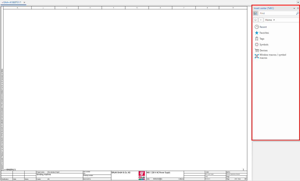
When a page has been opened in which symbols can be inserted, the Insert center will appear to the right of the page.
Insert symbol
From there, you can select the Symbols section and choose the required symbol from the libraries. For the most commonly used multi-line diagrams, the IEC_symbol library will be used.

Next is the choice of category. This category is very important. There can be similar or even identical symbols in different categories (for example, a switch, a push-button or an auxiliary contact of a relay or contactor), and while the designers or anyone else for that matter can read the schematics and orient themselves by the visual appearance of the symbol, EPLAN has a so-called “function definition” stored as part of each symbol that states that it is an auxiliary contact (and should be shown as a link in the contact field) or if it is a main device: a push-button.
Tags can be created to make the selection of symbols much more efficient. At the start, tags can be defined as a company standard for the most used symbols, devices, and macros. Company standard schemes can be imported with the following instructions.
The symbol can then be placed into the diagrams by dragging from the Insert center or by double-clicking the symbol. Before inserting the symbol with the left mouse button, it is still possible to rotate and/or mirror the symbol with the [Tab] key.
Grid
Symbols inserted into pages are always attached to the defined grid. This is important because, in EPLAN, connections are never drawn directly, but are created as a result of two connection points that are aligned and orientated with each other.
The standard grid for IEC Symbols and other known standards is C i.e., 4mm. The connection pitch for multi-line symbols such as 3-phase power contacts is 8mm in standard libraries. Therefore, it is highly recommended that this grid dimension is not changed so that there are no issues with matching the connection points.
After placing the symbol, the following properties dialog will appear:
In this article, only the most important features of the device will be highlighted.
Displayed DT (Device Tag) and Full DT
The visible marking or tag as what is seen next to the given symbol. To define the device that the symbol is supposed to represent, it is necessary to always look at the Full DT. This must be unambiguous in the given project and consist of the designation of the superior function. For the contactor from the example above it is the Function Designation =GAA and it may be the switching of the power supply and is most often taken from the Full Page Name. The Location Designation in this case +A1 is its physical location which may be the enclosure in which it is mounted and again is most often taken from the Full Page Name. The product designation -QA1 is the designation of the contactor within the Function and Location.
Connection point designation and description
These designate and describe all the connection points on the symbol. In the example, the coil has two connection points A1 and A2. It can be U, V, W, PE for a motor, 13 and 14 for a normally-open contact etc. It is important to separate the individual connections with a line break: ¶. This can be added using the keyboard shortcut CTRL+Enter or by the right-mouse-button context menu > Line break.
Technical characteristics
They are not normally entered manually but are updated automatically once a part has been assigned.
Function text
Here a given function can be entered describing what the device actually does e.g., Start, Forward, Reverse, etc.
Main function
Probably the most important field. Each device must have exactly one Main Function activated but may have any number of auxiliary functions (symbols with the same Full DT but Main Function deactivated). For example, on a relay or contactor coil, the Main Function is active. This is where the part number of the contactor or relay is specified. Auxiliary functions will then be power contacts and/or auxiliary contacts. These have the same Device Tag, which will create cross-references between them, but will not have an active Main Function.
It is with the combination of the complete designation and the main function that complex devices are created. More on this topic in the article, 'device navigators'.
Inserting the device
Similar to the way symbols are organised, devices are divided into categories according to their use or function. For example, there is no such thing as a general contactor only specific devices from specific manufacturers. After selecting the desired device, EPLAN selects a suitable symbol. If this symbol is not quite suitable, it can be changed easily using the Backspace key.
After insertion, the same dialog as for the symbol will then appear, only this time some data is already pre-filled and the device part number is defined in the parts tab.
More on managing parts in the separate article Parts Management.
Insert tab
Apart from the symbol libraries, where there are special types of symbols directly representing different types of devices. These special symbols can be inserted directly from the Insert tab. Here are a few of the most important ones.
1. Connection symbols
As mentioned above, connections are created automatically when opposing connections are aligned with each other. However, if the connection needs to change direction, be transferred to another page (interrupted), be removed, or a branch created, there are symbols specifically designed for these purposes.
2. PLC and Black boxes with PLC and device connection points
These symbols are used to construct complex devices, such as converters or power supplies, for which there is a standard symbol is not suitable.
3. Structure box
These are used to change the Function and/or the Location Designation for embedded symbols. For example, a motor is not normally located in the enclosure. By placing it in this box, it can be assigned to a different location than the one inherited from the page (e.g., +T, +S, etc.)
To use other functions, such as PLCs, cables, terminal strips, plugs and sockets, follow our other blog articles or take a look at the specialised training courses.

Comments